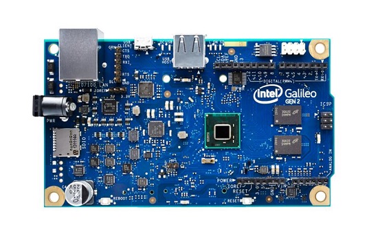
 galileo-motherboard.jpg
Figure 1– Intel® Galileo Gen2 Board
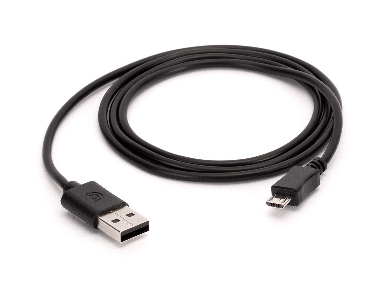
Figure 2- You’ll need one of these USB cables.
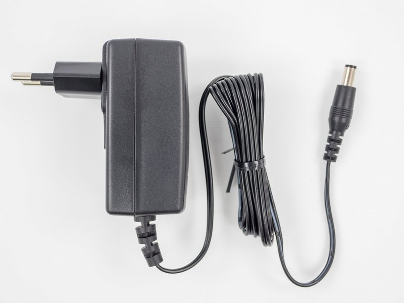
Figure 3- You’ll also need one of these power cables.
To upload Arduino sketches the Intel® Galileo board must be powered up and connected to your computer.
Plug in the DC power supply into an outlet and into DC barrel jack on your Intel® Galileo board. You should see the green power LED light up near the USB port on the board. NOTE: If you are using the DC power supply included with the Intel® Galileo make sure you fit the apropriate plug.
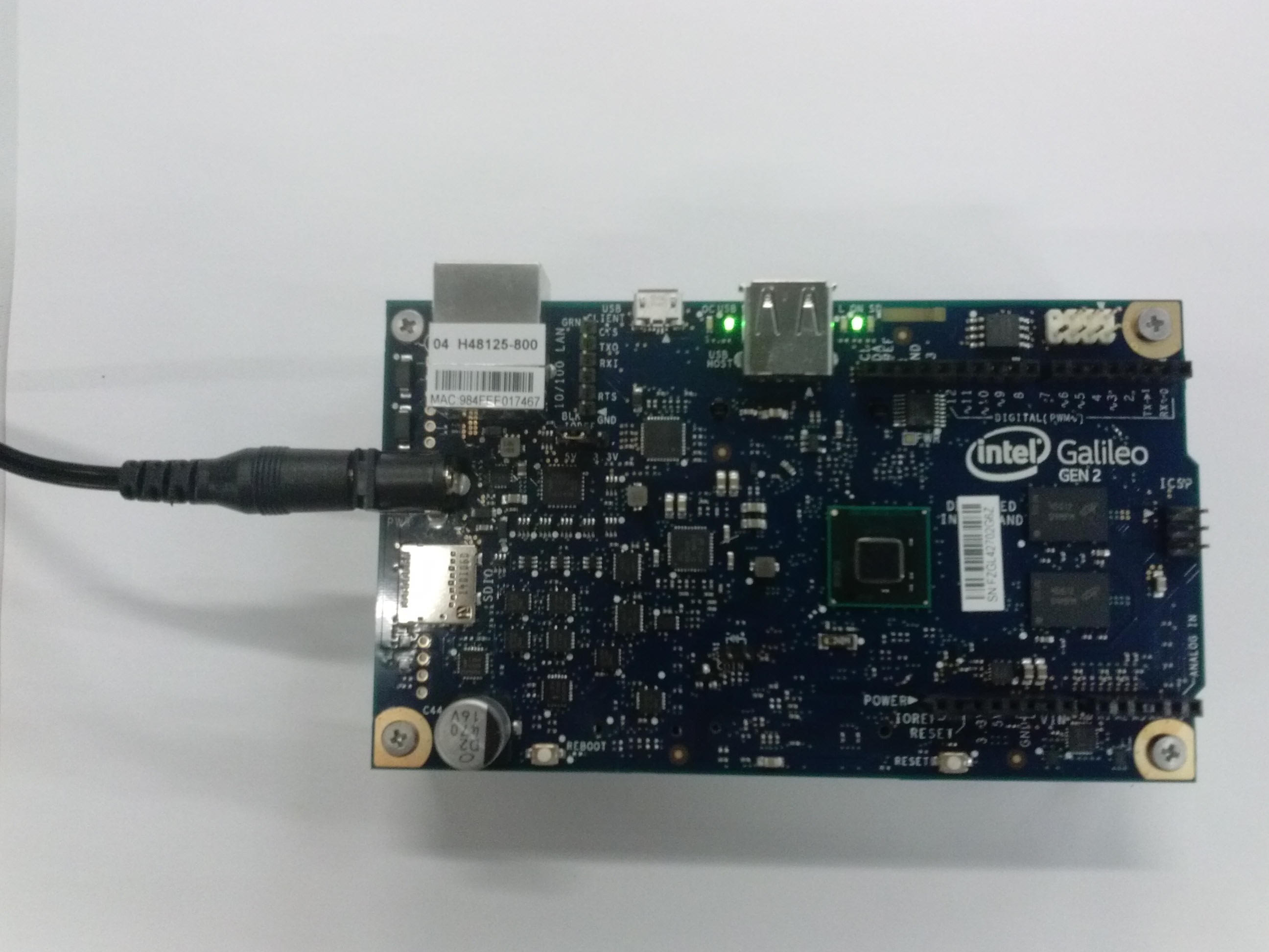
Figure 4- Intel® Galileo board with DC power plugged in and power LED lit
Plug the micro-USB cables to the micro USB connector on the board.
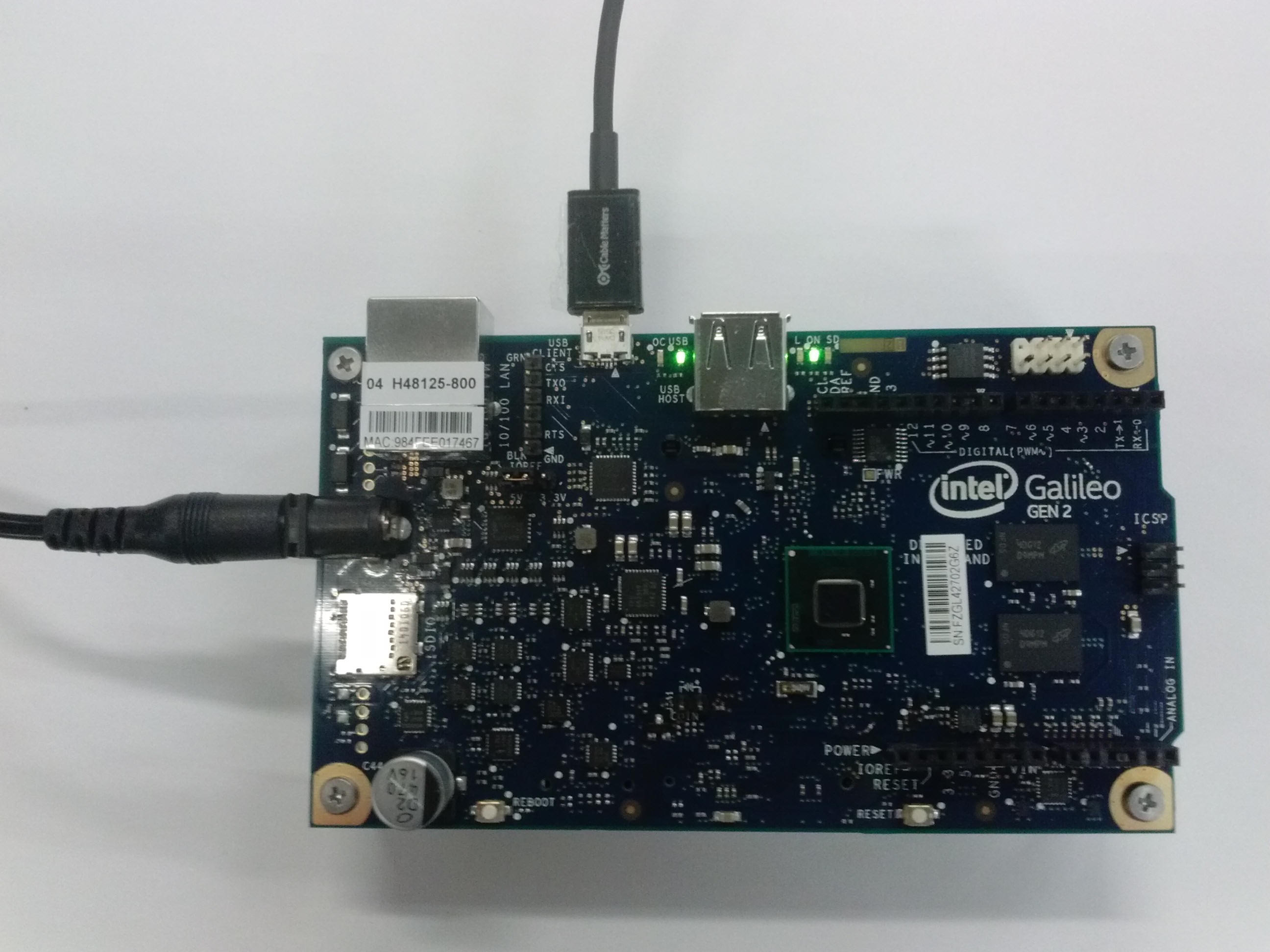
Figure 5- Plug in USB cable into the micro USB port
Plug in other end of the usb cable to your computer.
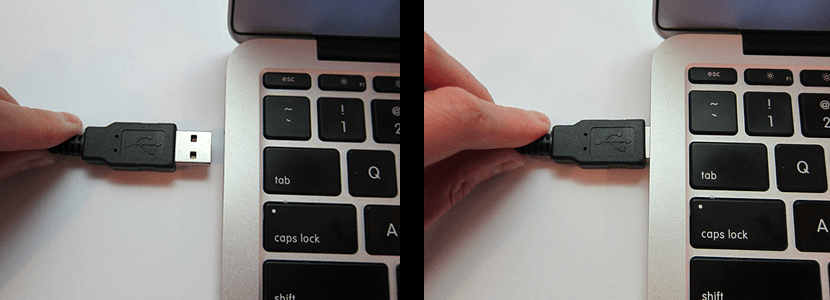
Figure 6- Plug the other end of the USB cable into your computer USB port
Wait a moment for the board to boot up. If you are plugging in your board for the first time and using Windows your computer will begin a driver install process. Allow this to complete before contining on.
Open the LED blink example sketch: File > Arduino Examples > 1.Basics > Blink. You should see a window similar to the one below.

Figure 7- Blink example loaded into Arduino IDE
You'll need to select the Intel® Galileo in the Tools > Board menu.
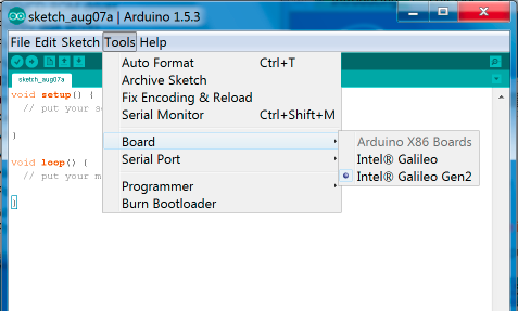
Figure 8- Select Intel® Galileo Gen2 from the Tools > Board menu
Select the serial device of the board from the Tools | Serial Port menu. The easiest way to find what port the board is using is by disconnecting your board, restarting the IDE, and re-opening the menu; the entry that disappears should be the Intel® Galileo board. Reconnect the board, restart the IDE, and select that serial port.
On Windows* Systems
The port is likely to be COM3 or higher in the Device Manager, like in Figure 9. COM1 and COM2 are usually reserved for hardware serial ports.
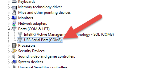
Figure 9- Select Intel Galileo Com Port (COM#)

Figure 10- Select COM port from Tools > Serial Port menu is using Windows*
Now the bottom right should match the COM port number of the 'Intel Galileo Virtual Com Port (COM#)' from the Device Manager, like in Figure 11.

Figure 11- The COM number should match the Intel Galileo Virtual Com Port (COM#).
On Linux*
The port is likely to be /devlab/ttyACM0.
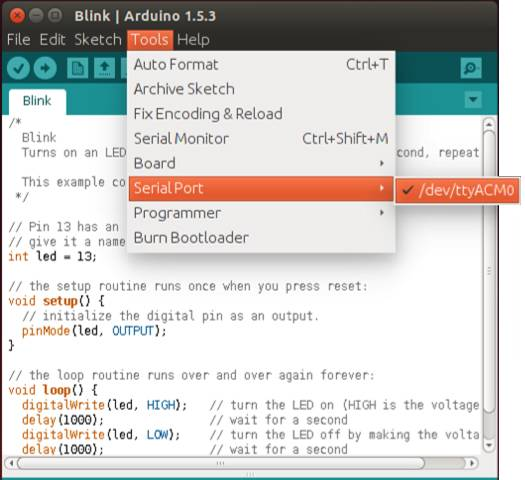
Figure 12- Select /devlab/ttyAMC0 from the Tools > Serial Port menu is using Linux*
On Mac OS X*
The port is likely to be /devlab/cu.usbmodemxxxx.
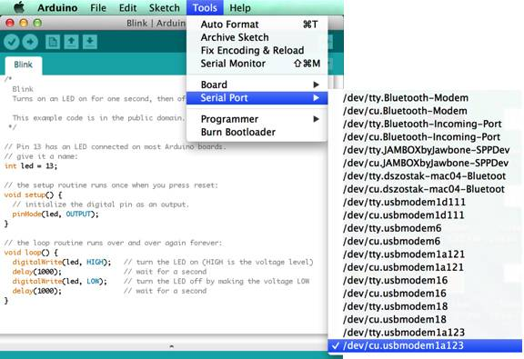
Figure 13- Select /devlab/cu.usbmodemxxxx from the Tools > Serial Port menu is using OS X*
Click the Upload button in the upper left to load and run the sketch on your board.

Figure 14- Click the Upload button to upload and launch your sketch
You should see a 'Done Uploading' and a 'Transfer complete' when it has uploaded, like in Figure 15.

Figure 15- You should see 'Transfer complete'
The DS2 LED on your board should now blink with a 1 second delay.
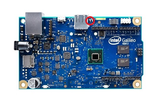
Figure 16- The LED closest to the USB port should now blink with a 1 second delay.